
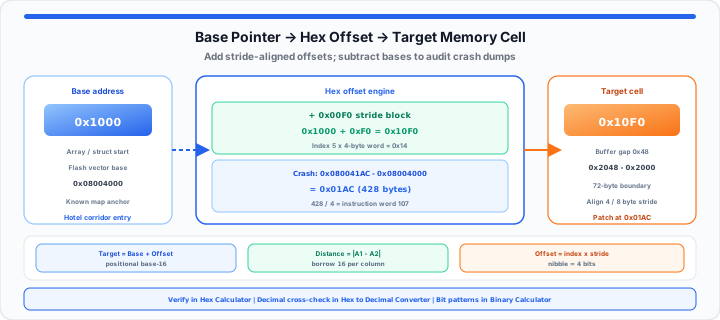
A custom firmware driver throws an immediate segmentation fault. An unmapped loop index drops corrupted bytes across protected register arrays. The console dumps a raw memory address crash log. The entire embedded system halts cold during production testing. Engineers face the cold panic of manual address calculations. When I dump raw register states at the console, panic strikes. Straining your eyes over raw memory dumps creates severe fatigue. Manual base-16 pointer calculations frequently introduce devastating human errors.
Think of your hex memory grid as a strict address map. It is a base-16 layout built to lock down byte boundaries. Picture your RAM array as a massive luxury hotel corridor. The base address is the room number at the front entrance. Your target hex offset represents the precise distance down the hallway. It measures the exact step count to find a guest suite. Calculate the offset wrong, and you smash straight through a wall. You drop down an empty elevator shaft, corrupting system stability.
The Base-16 Radix Allocation
Alphanumeric Position Analysis and Base-10 Equivalence
To get started, master the base-16 positional system first. Hexadecimal uses sixteen distinct symbols to represent raw memory values. Digits zero through nine represent values zero through nine directly. Letters A through F represent values ten through fifteen cleanly. Each hexadecimal position represents an increasing power of sixteen. In my production firmware experience, alignment errors wreck execution paths. The rightmost digit multiplies by sixteen to the zeroth power. Moving left increases the positional exponent by one each time. Summing positional products yields the total base-10 byte count. Understanding positional weight simplifies complex memory dump analysis enormously.
Low-level compilers organize binary structures around sixteen-bit boundaries. Nibbles consist of four binary bits representing one hex digit. Two hexadecimal digits form one complete eight-bit byte unit. Four hex digits compose a sixteen-bit memory word value. Eight hex digits build a full thirty-two-bit address pointer. You can verify your baseline register math instantly with our Hex Calculator. Developers can simulate offset values with add, subtract, and bitwise modes, then cross-check decimal equivalents in the Hex to Decimal Converter.
Target Address = Base Address + Offset Value
Pointer Distance = |Address₁ − Address₂|
Byte Stride Limits and Register Multipliers
Hardware registers store data in strict multi-byte alignments. A thirty-two-bit system uses four-byte stride alignments for words. Sixty-four-bit architectures require eight-byte stride boundaries for pointers. Multiplying array indices by byte stride lengths yields exact offsets. An index of five on a four-byte array needs twenty bytes. Twenty base-10 converts directly to 0x14 in hexadecimal notation. Adding 0x14 to the base address isolates the target element. Proper stride math prevents accidental cross-boundary data corruption in memory. Misaligned memory access triggers hardware exceptions on ARM Cortex processors. Aligning data structures on power-of-two boundaries optimizes bus reads. Compiler padding fills gaps between mismatched struct field data types. Auditing struct alignment prevents hidden padding byte calculation errors. For pure base-2 carry chains without leaving hex notation, pair this workflow with the Binary Calculator and our guide on adding binary numbers without decimal conversion.
| Hex Symbol | 4-Bit Binary Pattern | Base-10 Integer Value | Hardware Byte Boundary Metric |
|---|---|---|---|
| 0xA | 1010 | 10 | Half-word upper boundary marker |
| 0xB | 1011 | 11 | Odd-byte structural boundary offset |
| 0xC | 1100 | 12 | Quad-byte instruction word alignment |
| 0xD | 1101 | 13 | Extended stack pointer frame index |
| 0xE | 1110 | 14 | Vector table offset indicator slot |
| 0xF | 1111 | 15 | Maximum single-nibble register allocation |
The Relative Offset Disruption
Isolating Buffer Overflows and Structural Array Boundaries
Moving onto buffer boundaries, calculating relative distance prevents catastrophic failures. Buffer overflows happen when data writes exceed allocated memory boundaries. An attacker sends oversized payloads to overwrite function return pointers. In our memory corruption testing, tracking exact byte distances is vital. Subtract the target buffer start address from the saved pointer. The resulting difference represents the exact required exploit payload length. Consider a buffer starting at address 0x2000 in RAM. The return address location resides further up at address 0x2048. Subtracting 0x2000 from 0x2048 yields an offset of 0x0048. Hexadecimal 0x0048 converts directly to seventy-two decimal bytes. Writing seventy-two bytes reaches the return address boundary precisely. Seventy-three bytes overwrite the pointer, controlling system execution flow. Precise byte calculation prevents accidental corruptions of adjacent stack variables. Security research requires exact offset mapping during exploit payload development. Vulnerability remediation demands precise boundary checks in C software code. Engineers verify bounds before accepting raw user input data blocks. Analysts can test custom code block variables during audits and decode payload bytes with the ASCII Converter when dumps mix text and hex.
Two's Complement Boundary Overflow Rules
Relative branch instructions in assembly use signed hexadecimal offsets. Negative offsets allow loops to jump backward in executable code. Signed hex values utilize two's complement binary encoding representations. A hex offset of 0xFF represents negative one byte distance. Offset 0xFE indicates a backward jump of two bytes. Miscalculating signed offsets causes infinite loops or execution crashes. Firmware developers verify signed boundary limits during low-level optimization. Stack frames grow downward toward lower memory addresses in x86. Heap allocations grow upward toward higher memory address ranges. Understanding growth directions prevents stack-heap collision bugs in embedded systems. Two's complement subtraction mechanics are covered step-by-step in our binary addition and subtraction guide.
The Production Segment Pointer Audit
Practical Firmware Debugging Blueprint
In practical environments, forensic crash analysis requires systematic address verification. Investigating memory corruption requires tracking nested pointer differences carefully. A malicious payload alters execution paths by exploiting weak checks. Engineers trace raw instruction pointer values to locate injection vectors. Below are primary diagnostic attributes from a production incident trace.
- Target Crash Address: 0x080041AC extracted from instruction register.
- Vector Base Pointer: 0x08004000 defined in flash memory map.
- Calculated Hex Difference: 0x080041AC − 0x08004000 equals 0x01AC offset.
- Decimal Byte Offset: Hex 0x01AC converts to 428 decimal.
- Fault Location Pinpoint: Routine fails at byte 428 inside driver.
- Instruction Word Offset: 428 divided by 4 equals 107.
- Disassembly Inspection: Inspect instruction 107 inside source code binary.
- Remediation Action: Patch boundary check at offset 0x01AC immediately.
Isolating exact byte offsets accelerates vulnerability patch deployments across teams. Automated register tracking eliminates guessing during critical firmware recovery sessions. Systematic pointer auditing builds resilient, secure embedded firmware architectures. Firmware engineers document base offset mappings inside peripheral register maps. Clear register offset documentation simplifies team code maintenance and review. Debugging microcontrollers requires constant validation of physical memory addresses. Hardware watchpoints trigger breaks when code writes across offset limits. Analyzing crash dumps becomes faster when offset calculation patterns are standardized. Network packet captures use the same octet-to-hex mindset — see How Network Engineers Parse Raw IPv4 Addresses to Hex Formats and the IP Address Converter. API payload debugging often starts with text-to-hex conversion for request bodies.
Open Hex Calculator Open Hex to Decimal Converter
Frequently Asked Questions
How do you calculate a hexadecimal memory offset manually?
Subtract the base memory address from the target address. Perform base-16 subtraction column by column from right to left. Borrow values equal sixteen when subtracting larger digits from smaller. The resulting hexadecimal value represents the exact memory offset distance.
Why does low-level firmware utilize base-16 calculation sheets for register debugging?
Hexadecimal aligns perfectly with four-bit binary nibbles in hardware. A single byte represents two clean hexadecimal characters in memory. Base-16 reduces human error compared to long binary digit strings.
What is the difference between relative offsets and absolute memory addresses?
Absolute addresses point to fixed locations inside physical memory chips. Relative offsets measure distance spans from a known base pointer. Offsets allow position-independent code execution across varying memory layouts.
How do stride lengths affect array pointer calculations in assembly?
Stride length specifies the byte size of individual array elements. Multiply array index by element stride to calculate memory offset. Add offset to base array address to target specific elements.