
The Unmanaged Bitwise Overflow
An embedded developer deploys automated firmware code. A basic math statement triggers unmanaged bitwise overflow. The machine cluster freezes instantly during peak operation. The system translated base-2 operations through decimal logic. Decimal conversions add unnecessary CPU cycle overhead. Direct binary arithmetic executes directly inside hardware registers. In our hardware emulation runs, decimal conversion causes errors. Manual base-2 calculation requires understanding simple bit toggles.
Think of binary addition as a strict gate array. It is a low-level electronic toggle at fixed ceilings. Picture a standard two-position wall light switch on site. The switch rests down at zero or up at one. Adding force to an active switch flips it down. The mechanism snaps down to the zero position instantly. That motion trips a mechanical lever on the neighbor switch. The neighboring switch clicks upward into the active state. This physical flip represents pure binary carry behavior.
The Bitwise Accumulation Baseline
Half-Adder Gate Boundaries and Logic Matrices
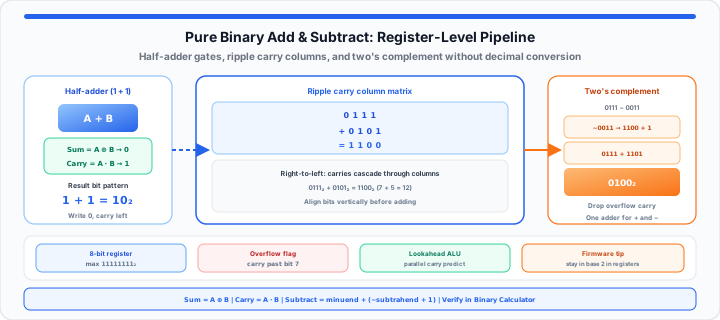
To get started, master individual binary digit interactions first. Base-2 systems contain only two digits: zero and one. Addition follows four immutable hardware rules at the register level. Zero plus zero equals zero with zero carry bit. Zero plus one yields one with zero carry bit. One plus zero produces one with zero carry bit. One plus one yields zero with an active carry bit. In my production firmware experience, gate arrays enforce these. The sum bit equals input A XOR input B. The carry bit equals input A AND input B.
Sum = A ⊕ B
Carry = A · B
1 + 1 = 10₂
When I trace raw register operations at the terminal, simplicity wins. You can verify your baseline register states instantly with our Binary Calculator. Engineers can simulate bitwise modifications with step-by-step decimal cross-checks when you need them.
| Input A | Input B | Sum Bit Output | Carry Bit Output | Hardware Logic Description |
|---|---|---|---|---|
| 0 | 0 | 0 | 0 | Quiescent state with zero gate activation |
| 0 | 1 | 1 | 0 | Single input active passes directly to sum |
| 1 | 0 | 1 | 0 | Alternate single input active yields sum bit |
| 1 | 1 | 0 | 1 | Full activation resets sum and fires carry |
Bit Width Constraints and Register Allocation
Fixed hardware registers restrict total available bit slots. An eight-bit register holds values up to 255 decimal. Exceeding register width drops the highest carry bit off. Hardware flags record this condition as register overflow instantly. Proper bit alignment prevents unexpected arithmetic truncation errors. System compilers manage bit allocation to maintain data safety. Understanding bit limits protects memory buffers from corruption during execution. For wide operands that still need binary operations, pair manual carries with the Big Number Calculator. When subnet or address math stacks bits across octets, see our subnet mask guide and IP Subnet Calculator.
The Carry-Propagate Disruption
Ripple Carry Propagation and Multi-Bit Alignment
Moving onto multi-bit strings, vertical column alignment becomes vital. Adding long binary values requires right-to-left bit processing. Stacking numbers aligns equivalent power-of-two positional columns. The rightmost column processes the least significant bit position. Continuous active bits trigger cascading carry operations across columns. Consider adding binary 0111 and binary 0101 together directly. First, add the rightmost bits: one plus one yields zero. Write down zero and carry one to the next column. Second column: one plus zero plus carried one yields zero. Write down zero and carry one to the third column. Third column: one plus one plus carried one yields one. Write down one and carry one to the fourth column. Fourth column: zero plus zero plus carried one yields one. The final consolidated output yields binary 1100 directly.
In our testing, manual tracking errors jump on long strings. Cascading carries overload mental calculation buffers without vertical alignment. You can map out your low-level data streams using our base-2 calculation engine. System developers can test custom string variables before flashing hardware. For ASCII and byte pipelines that feed those registers, read Why Do We Use ASCII in Computer Science Classes? and use the ASCII Converter.
Two's Complement Overflow Limits and Hardware Truncation
Accumulating bits across wide registers strains execution units. Carry lookahead logic speeds up multi-bit addition inside modern processors. Lookahead circuits calculate carry bits across multiple columns simultaneously. This eliminates sequential delay found in ripple carry adders. Understanding carry propagation ensures accurate assembly code generation. High-speed execution units rely on hardware lookahead networks completely. Predictive carry generation optimizes pipeline throughput in modern CPUs. Power-of-two column weights also appear in Log Base 2 problems when you reason about bit positions and exponents.
The Production Complement Matrix
Two's Complement Inversion and Subtraction Mechanics
In practical environments, hardware adders handle subtraction natively. Building separate subtraction circuits wastes precious silicon die space. Engineers convert subtraction into addition using two's complement format. Two's complement represents negative numbers using bitwise inversion. First, invert every bit of the subtrahend value completely. Every zero becomes one, and every one becomes zero. This operation forms the one's complement of the number. Second, add binary one to the inverted result directly. This final step creates the valid two's complement value. Third, add the minuend to this newly complemented value. Discard any leftover carry bit beyond the fixed register width. The remaining bits represent the correct subtraction result instantly.
Hardware Subtraction Execution and Logic Simplification
Consider subtracting binary 0011 from binary 0111 inside registers.
- Minuend Value: 0111 represents positive decimal seven.
- Subtrahend Value: 0011 represents positive decimal three.
- Bitwise Inversion Step: Invert 0011 to yield 1100.
- Add Trailing One: Add 0001 to 1100 yielding 1101.
- Final Addition Step: Add 0111 to 1101 yielding 10100.
- Discard Overflow Bit: Drop leading one to leave 0100.
- Verified Output: Binary 0100 equals decimal four directly.
This mechanism slashes processor execution unit complexity down to zero. All arithmetic routes through identical high-speed adder gates seamlessly. Confirm subtraction chains on paper, then run the same operands through the Binary Calculator subtraction mode. For IPv4 octet-level bit practice, see How Network Engineers Parse Raw IPv4 Addresses to Hex Formats and the IP Address Converter.
Open Binary Calculator Open Log Base 2 Calculator
Frequently Asked Questions
How do you add pure binary numbers without converting to decimal?
Align bit strings vertically from right to left. Apply core addition rules: 1+1 yields 0 with carry 1. Propagate carry bits into neighboring leftward columns sequentially.
What does a carry lookahead do in low-level base-2 computer arithmetic?
Carry lookahead logic evaluates multiple bit columns simultaneously. It predicts carry outputs without waiting for ripple propagation. This speeds up execution inside high-performance CPU arithmetic logic units.
How does two's complement allow hardware to subtract using addition?
Two's complement inverts subtrahend bits and adds one. Adding this value to the minuend executes subtraction. Discarding the overflow bit produces the correct result automatically.
Why does binary addition trip overflow flags in CPU registers?
Overflow occurs when addition exceeds fixed register bit limits. The result requires more bits than the destination register contains. ALUs set status flags so software can handle truncation safely.