
The Fried Amplifier Circuit
A burnt resistor destroys an audio channel rail instantly. In our bench diagnostics, guessing component values creates disasters. A technician replaced a swollen capacitor on vintage hardware. They misread a scorched resistor ring by eye alone. Powering up the board fried two amplifier transistors. Staring at tiny painted rings under microscopes causes severe eye strain.
Think of your resistor color rings as a physical barcode. They form a visual map built to expose Ohmic boundaries. Imagine a combination lock attached to a water valve. The first two rings represent primary combination numbers. The third ring acts like an adjustable valve handle. It exponentially expands or chokes down raw volumetric pressure. Misinterpreting one band turns a trickle into a flood. Mastering color codes restores precision to circuit board repairs. Accurate identification keeps sensitive hardware components safe from over-current destruction. You can simulate component bands with the Resistor Color Code Calculator before ordering replacements.
The Significant Digit Baseline
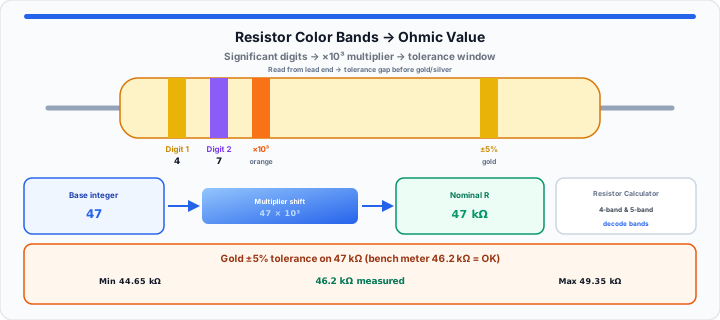
To get started, decode the initial positional color bands. The first bands state raw significant integer values. Reading starts from the band closest to the lead edge. A wider gap marks the final tolerance ring position. When I analyze burned-out micro-rails under the microscope, alignment matters. Positional values set the structural foundation for resistance metrics. Technicians verify baseline circuit metrics instantly in the decoder. Proper band identification eliminates guesswork during delicate board repairs. Every color holds a permanent position in the international standard. Misreading the first digit invalidates the entire Ohmic calculation. Inspect cleaned leads under bright lighting to avoid color confusion. Faded paint on scorched components often requires microscopic inspection. Comparing damaged parts against schematic diagrams confirms true values. After you know R, size current and power with the Ohm’s Law Calculator and our DIY Ohm’s Law maker guide.
4-Band versus 5-Band Structural Layouts
Four-band resistors display two significant digit rings. Five-band precision resistors include three significant digit rings. The extra digit provides tighter Ohmic resolution on schematics. High-precision audio circuits rely heavily on five-band components. Always count total rings before calculating base resistance values. Five-band resistors allow finer adjustments in sensitive analog stages. Modern surface-mount rework often mirrors these precision color standards. Six-band resistors add a thermal coefficient ring at the end. Understanding band counts prevents miscalculating total Ohmic ratings.
Primary Integer Alignment Rules
Each painted color corresponds to a specific numerical integer. Black represents zero in all significant digit positions. Brown maps directly to the number one integer. Red designates two, while orange defines three. Yellow equals four, and green represents five. Blue maps to six, violet equals seven. Gray represents eight, while white yields nine. Memorizing this numerical order speeds up bench troubleshooting. Formula alignment for four-band parts:
Base Integer = (Digit1 × 10) + Digit2
For five-band resistors:
Base Integer = (Digit1 × 100) + (Digit2 × 10) + Digit3
Consistently applying integer rules prevents costly circuit wiring mistakes.
The Base-10 Multiplier Shift
Moving onto Ohmic scaling, the multiplier ring shifts magnitude. The multiplier multiplies base digits by power-of-ten factors. A single color mistake alters resistance by orders of magnitude. A ten-ohm line suddenly becomes a ten-thousand-ohm barrier. In my component sourcing experience, misread multipliers destroy power rails. Builders can test wire and load metrics during bench assembly with the Ohm’s Law Calculator. For long copper runs after the resistor network, use the Voltage Drop Calculator. Proper scaling keeps voltage regulators within tight operational tolerances. Multipliers convert tiny base numbers into massive physical resistance fields. Always verify multiplier colors under balanced white bench lighting. Shadows and glare often cause orange and red color confusion.
Fractional Gold and Silver Multipliers
Sub-ohm sensing circuits require fractional power-of-ten multipliers. Gold bands scale base numbers by point one. Silver bands scale base numbers by point zero one. A red-violet-gold combination yields a two-point-seven ohm value. Current sense rails depend on fractional multiplier precision. Low-resistance shunts protect power supplies from over-current damage. Misinterpreting a gold multiplier creates severe short-circuit risks.
Metric Prefix Scale Adjustments
Ohms convert cleanly into kiloohms and megaohms. One thousand ohms equals one kiloohm metric unit. One million ohms forms one megaohm metric unit. Formula calculation follows:
Resistance Value = Base Integer × 10Multiplier
Expressing large values in metric prefixes simplifies schematic notation. Standardizing unit labels prevents conversion errors across engineering teams.
| Band Color | Significant Digit | Power-of-Ten Multiplier | Standard Tolerance Rating |
|---|---|---|---|
| Black | 0 | 100 (×1) | — |
| Brown | 1 | 101 (×10) | ±1% |
| Red | 2 | 102 (×100) | ±2% |
| Orange | 3 | 103 (×1K) | — |
| Yellow | 4 | 104 (×10K) | — |
| Green | 5 | 105 (×100K) | ±0.5% |
| Blue | 6 | 106 (×1M) | ±0.25% |
| Violet | 7 | 107 (×10M) | ±0.1% |
| Gray | 8 | 108 (×100M) | ±0.05% |
| White | 9 | 109 (×1G) | — |
| Gold | — | 10−1 (×0.1) | ±5% |
| Silver | — | 10−2 (×0.01) | ±10% |
The Production Tolerance Boundary
In practical environments, components deviate from nominal values. The tolerance ring establishes acceptable manufacturing variance limits. No physical resistor measures its exact marked value perfectly. Temperature shifts and manufacturing flaws cause internal variances. A gold ring designates a five percent tolerance boundary. A silver ring establishes a ten percent tolerance boundary. Brown bands mark precision one percent tolerance boundaries. Precision military hardware uses red bands for two percent bounds. Tighter tolerances guarantee consistent performance in high-frequency circuits. Testing components with a multimeter verifies compliance before soldering. Out-of-spec resistors alter bias currents across sensitive transistor bases.
Thermal Coefficient Constraints
Six-band resistors include a thermal coefficient ring at the end. This ring tracks resistance drift per degree Celsius change. PPM values dictate thermal stability during heavy current loads. High-temperature environments alter unrated resistor behavior severely. Audio amplifiers need low PPM ratings to prevent thermal runaway. Precision test gear requires temperature-stable resistors across all stages.
Safe Operational Voltage Deviations
Calculating variance prevents over-voltage damage across board rails.
Allowed Variance = Nominal Value × Tolerance Percentage
Maximum Resistance = Nominal Value + Allowed Variance
Minimum Resistance = Nominal Value − Allowed Variance
Measuring values beyond calculated bounds indicates component degradation. Core diagnostic metrics from a live bench audit:
- Nominal Component Value: 47,000 Ohms base schematic rating.
- Tolerance Band Rating: Gold band 5 percent variance boundary.
- Calculated Variance Margin: Plus or minus 2,350 Ohms allowance.
- Minimum Allowable Limit: 44,650 Ohms lower threshold limit.
- Maximum Allowable Limit: 49,350 Ohms upper threshold limit.
- Measured Bench Reading: 46,200 Ohms verified meter measurement.
- Diagnostic Component Status: Verified safe within operational boundaries.
Quick decode: Select yellow, violet, orange, gold in the Resistor Calculator for 47 kΩ ±5% as in the worked tolerance example above. Then confirm wattage with P = V²/R.
Open Resistor Calculator Open Ohm’s Law Calculator
Frequently Asked Questions
How do you calculate resistor color codes manually?
Identify the first two or three significant digit bands. Convert the color bands into their corresponding numerical integers. Multiply the base integer by the power-of-ten multiplier. Apply the tolerance percentage to determine acceptable variance limits.
Why does a 4-band resistor differ from a 5-band system?
Four-band resistors utilize two bands for significant digits. Five-band resistors utilize three bands for significant digits. Five-band components deliver higher resolution for precision circuits.
How do you identify the first band on a resistor?
Look for the band closest to a metal lead end. Tolerance bands often sit separated by a wider gap space. Gold and silver bands never appear as the first digit.
What happens if a resistor operates outside its tolerance boundary?
Out-of-spec resistors alter current delivery across circuit branches. Excessive current can overheat adjacent silicon components quickly. Replace any component measuring outside its calculated tolerance window.