
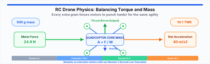
High-KV motors look impressive on spec sheets. However, pairing them with heavy frames causes major problems. On test benches, excess mass destroys cornering response. Builders often install heavy 3D-printed TPU arms. Then, their electronic speed controllers overheat instantly. The quadcopter feels sluggish during fast pitch flips.
Think of Newton's second law as a strict weight penalty box. Every extra gram requires your motors to punch harder. This maintains basic hover agility under heavy aerodynamic loads. Redirecting a heavy quad resembles swinging a bowling ball on a rope. The momentum resists rapid trajectory changes during freestyle dives. Proper physics balance resolves these torque tax problems cleanly. Unbalanced quadcopters waste energy fighting inertia instead of generating speed. Proper component selection preserves flight agility and extends battery runtime.
The Inertial Mass Baseline
To get started, dry frame mass dictates baseline kinetic resistance. When evaluating a carbon fiber frame, every gram counts. Total curb weight includes battery, motors, and camera payload. Dry frame weight represents static baseline mass without active payload. Every electrical connector and motor wire adds to net vehicle weight. Trimming excess wire length reduces parasitic mass across your build. Linear acceleration depends directly on total vehicle mass metrics. The fundamental acceleration relationship follows standard classical physics equations:
A = F ÷ M
Frame Weight versus Dynamic Momentum
Excess weight increases linear inertia during sharp hairpin turns. Heavy quads drift outward when executing crisp tight turns. On test benches, lighter arms decrease motor response lag. Thicker carbon plates add structural rigidity but increase overall mass. Flexible arms cause motor vibrations, forcing higher PID loop filtering. Higher filtering introduces latency into control feedback loops. Carbon fiber weaves affect frame stiffness under heavy motor torque loads. Stiffer frames transfer mechanical motor thrust directly to linear movement. Flexing carbon frames waste kinetic energy through harmonic arm oscillations.
You can verify your frame's inertia curve with our Newton's Second Law Calculator. Target minimal dry mass to maximize dynamic control authority.
Battery Weight Allocation and Inertia
Battery placement shifts your quadcopter mass distribution center dramatically. Top-mounted packs alter polar moment of inertia differently than bottom mounts. Centralizing battery mass close to prop planes improves roll authority. Extending mass outward increases resistance against rapid axis flips. Heavy battery packs require higher continuous torque output from motors. Lipos placed far from center axis increase rotational inertia resistance. Keeping heavy components near axis centers minimizes torque required for flips. This drains current rapidly during high-G evasive maneuvers.
Instant Tool: Simulate your acceleration metrics with our interactive Newton's Second Law Calculator. Proper mass distribution stabilizes pitch axis balance during aggressive flights.
The Rotational Thrust Vector
Moving onto propulsion, motors generate raw torque for propeller loads. Thrust profiles change based on air density and pitch blade angles. Aerodynamic drag on propeller blades increases exponentially at higher RPMs. Efficient motors generate required torque without drawing excessive battery current. Absolute force output must overcome overall vehicle curb weight.
Brushless Motor Stator Torque Dynamics
Larger stator sizes generate substantially higher low-end mechanical torque. A 2207 stator handles high-pitch props better than smaller 2205 stators. Stator height influences high-RPM power curves significantly. Stator width dictates instantaneous low-RPM magnetic torque output. Stator volume determines maximum electromagnetic force capability under load. Taller stators increase high-RPM power efficiency on straightaway tracks. Wider stators increase immediate rotational torque for rapid pitch directional changes. Wider stators handle heat efficiently. Higher torque output ensures immediate RPM corrections during fast roll maneuvers. N52H curved magnets provide stronger magnetic coupling across stator gaps.
Always test your custom build specs before buying motors. Matching torque to propeller mass prevents speed controller desyncs.
Propeller Pitch Load Constraints
Steep propeller pitch delivers higher top speeds at full throttle. However, aggressive pitch increases mechanical motor load significantly. Heavy pitch blades stall at low flight speeds during sharp cornering. Stalled blades generate unwanted drag rather than useful thrust forces. High-pitch props require higher motor stator torque to reach max RPM. Low-pitch props spin up faster, improving low-end throttle response time. Selecting proper pitch optimizes battery efficiency and cornering acceleration output. This extra load demands more amperage from your LiPo battery. Reduced rotor acceleration limits crisp low-end freestyle control response. Tri-blade designs provide better cornering grip than bi-blade propellers.
Builders can map out physics variables using our free Force Calculator. Optimal pitch balances maximum thrust against rotational prop inertia.
Drone Mass and Torque Conversion Matrix
| Frame Category | Frame Mass (g) | Motor Stator Size | Propeller Pitch | Min Thrust Ratio | Max Acceleration (m/s²) |
|---|---|---|---|---|---|
| Micro Racing | 120 | 1204 | 3.0 Inches | 6:1 | 49.0 |
| Ultralight Toothpick | 180 | 1404 | 4.0 Inches | 8:1 | 68.6 |
| 5-Inch Freestyle | 550 | 2207 | 4.3 Inches | 10:1 | 88.2 |
| 5-Inch Speedsprinting | 450 | 2306 | 5.0 Inches | 14:1 | 127.4 |
| Heavy Payload Cinema | 1250 | 2808 | 7.0 Inches | 4:1 | 29.4 |
The Real-World Flight Dynamics Test
In practical environments, dive pullouts test ultimate vehicle dynamics limits. A drone dropping vertically accelerates due to downward gravitational forces. Recovering before hitting the ground requires intense motor force generation. High-G turns force motors to operate at peak output. Simulating force requirements prevents dangerous prop wash instability during dives. Accurate math models ensure your quad pullout vector remains razor sharp.
Dive Recovery Force Calculation
Let us evaluate a typical 500-gram freestyle quadcopter scenario. The quad enters a high-speed vertical dive towards Earth. Downward gravitational acceleration equals exactly 9.81 meters per second squared. The frame mass equals exactly 0.50 kilograms in standard units. Downward gravitational force equals 4.905 Newtons of force. Aerodynamic drag provides minimal braking force during steep dives. To arrest descent instantly, net upward force must exceed gravity. Target vertical acceleration requires a minimum 40.0 meters per second squared. Total motor thrust required equals mass times target upward acceleration.
Fnet = m × atarget
Required net vertical force equals 0.50 kg times 40.0 m/s². This calculation yields 20.0 Newtons of required net force. Total motor thrust must equal net force plus gravity force.
Ftotal = Fnet + Fgravity
Total motor thrust requires 24.905 Newtons of output force. Dividing 24.905 Newtons by four motors yields 6.226 Newtons per motor. This translates directly to roughly 635 grams thrust per motor. Four motors combined must generate at least 2540 grams total thrust. Voltage sag reduces battery output under maximum throttle bursts. Target a thrust buffer to compensate for momentary voltage drops. This demands a 5.08 to 1 thrust-to-weight ratio minimum.
Open Newton's Second Law Calculator Open Force Calculator
Frequently Asked Questions
How does adding an action camera affect drone cornering physics?
Adding an action camera increases total vehicle curb mass directly. Higher mass increases linear inertia during sharp directional turns. Motors must work harder to change moving flight direction vectors. Cornering radius expands unless motor thrust output increases proportionally.
What is the ideal thrust-to-weight ratio for custom racing drones?
Competitive racing drones target a 10:1 thrust-to-weight ratio or higher. Freestyle drones operate effectively between 7:1 and 10:1. Higher ratios provide rapid vertical punchouts and tight dive recoveries. Lower ratios reduce maneuverability and increase motor thermal stress.
Why do heavy quadcopters overheat electronic speed controllers faster?
Heavy quadcopters demand continuous higher motor torque output during flight. Motors draw significantly more electrical current to offset mass inertia. Increased current draw causes resistive heating within speed controller MOSFETs. Reducing frame weight lowers current draw and drops ESC temperatures.
How does propeller pitch impact motor torque requirements?
Higher propeller pitch increases physical air resistance on spinning blades. Motors require higher mechanical torque to maintain set rotor RPMs. If torque is insufficient, motor acceleration lags behind throttle inputs. Matching prop pitch to motor stator torque ensures optimal response.
How does battery voltage sag affect thrust-to-weight calculations?
Voltage sag drops motor RPM under full throttle bursts. Lower voltage reduces overall force generation from brushless motors. Builders must calculate thrust ratios using sagged voltage levels. This ensures adequate control power during end-of-flight maneuvers.