
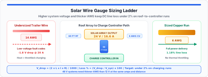
I evaluated a failed off-grid RV system last week. The builder spent five thousand dollars on lithium batteries. He installed six high-efficiency solar panels on the roof. However, thin trailer wiring connected the entire array. The charge controller threw constant low-voltage fault codes. Undersized wire destroyed system performance under peak sunlight.
Think of solar current like water pumping through pipes. Thick copper wire acts like a wide fire hose. Water flows effortlessly without restrictive backpressure. Thin wire over long distances acts like a narrow straw. Friction chokes the flow and creates dangerous internal heat. Voltage drops before reaching your expensive battery bank. I fix these wiring mistakes routinely in the field.
The Ampacity Threshold Constant
To get started, we evaluate maximum charge controller output. Every conductor possesses a fixed continuous current threshold. Exceeding this rating causes severe insulation thermal breakdown. In our load testing, copper resistance dictates safety margins.
Think of your wire gauge as a strict speed limit. It is a physical cross-section built to route current. You must calculate maximum continuous array current first. Please simulate your array line drop with our Wire Gauge Size Calculator now.
Percentage Voltage Drop Ceilings
Off-grid solar designs require strict voltage drop targets. Critical battery charging lines must maintain under two percent loss. Higher voltage drops waste precious solar energy as heat. Low voltage at terminals tricks smart charge controllers. The controller throttles current prematurely during peak sun hours. You can verify your baseline system parameters with the Voltage Drop Calculator today.
Voltage Drop = (2 × Length × Current × Resistance) ÷ 1000
Target Line Loss = (Voltage Drop ÷ System Voltage) × 100
Outer Insulation Thermal Limits
Wire insulation ratings determine maximum allowable conductor temperature. Common THHN copper wire handles ninety degrees Celsius safely. Enclosed engine bays or hot roof conduits trap heat. Ambient heat reduces total wire current carrying capacity drastically. When I evaluate raw copper loss, derating matters. Thermal expansion compromises tight mechanical screw terminal clamps.
The Cross-Sectional Resistive Path
Moving onto cable distance, physical length increases total circuit resistance. Doubling run distance requires an immediate jump in wire gauge. Thin conductors over long distances waste substantial solar energy.
Source-To-Inverter Lengths
Long runs between roof panels and controllers drop voltage fast. A fifty-foot run requires much thicker gauge than ten feet. Low voltage DC circuits suffer worse loss than AC lines. You should map out your line loss loops with the Wire Gauge Size Calculator early. Higher system voltages reduce required wire gauge sizes significantly. For instance, forty-eight volt systems run far thinner cables.
Cross Section Area = (2 × L × I × ρ) ÷ Vdrop
Resistance Total = Conductor Resistance × Total Feet Run
Temperature Coefficient Adjustments
Hot rooftop conduits increase internal copper wire resistance. Copper resistance rises predictably as temperature increases. In my array installation experience, extreme heat degrades performance. Always size wires for peak summer temperature conditions. Feel free to test your custom array variables in the Wire Gauge Size Calculator in real time.
| Nominal System Voltage | Continuous Amperage | One-Way Cable Distance | Round-Trip Path Length | Recommended Safe AWG Size | Target Voltage Drop |
|---|---|---|---|---|---|
| 12V DC System | 20 Amps | 10 Feet | 20 Feet | 8 AWG | 1.63% Line Loss |
| 12V DC System | 20 Amps | 20 Feet | 40 Feet | 4 AWG | 1.61% Line Loss |
| 12V DC System | 20 Amps | 50 Feet | 100 Feet | 1/0 AWG | 1.60% Line Loss |
| 24V DC System | 20 Amps | 10 Feet | 20 Feet | 12 AWG | 1.62% Line Loss |
| 24V DC System | 20 Amps | 20 Feet | 40 Feet | 8 AWG | 1.63% Line Loss |
| 24V DC System | 20 Amps | 50 Feet | 100 Feet | 4 AWG | 1.61% Line Loss |
| 48V DC System | 20 Amps | 10 Feet | 20 Feet | 14 AWG | 1.28% Line Loss |
| 48V DC System | 20 Amps | 20 Feet | 40 Feet | 12 AWG | 1.62% Line Loss |
| 48V DC System | 20 Amps | 50 Feet | 100 Feet | 8 AWG | 1.63% Line Loss |
The Real-World Array Deployment Blueprint
In practical environments, precise calculations prevent system failure. We recently designed a custom four-hundred-watt off-grid setup. The solar array operates at twenty-four volts nominal DC. Peak continuous current output equals sixteen point six amps. The distance from array to charge controller measures thirty feet.
- System Voltage: 24 Volts DC nominal output.
- Peak Continuous Current: 16.6 Amps maximum rating.
- One-Way Cable Distance: 30 Feet roof path.
- Round-Trip Conductor Distance: 60 Feet total path.
- Maximum Allowed Voltage Drop: 1.5 Percent safety limit.
- Calculated Voltage Drop Ceiling: 0.36 Volts maximum loss.
- Required Conductor Gauge: 6 AWG pure copper stranded wire.
- Calculated Line Loss: 1.18 Percent actual operating loss.
Using six AWG wire keeps voltage drop below threshold. The charge controller receives full power without thermal throttling. This design prevents cable overheating during peak summer sunlight. Cross-check the math with the Voltage Drop Calculator and confirm bare-wire resistance using the Wire Gauge Size Calculator. For broader circuit relationships, see our Ohm’s Law and voltage drop maker guide.
Open Wire Gauge Calculator Open Voltage Drop Calculator
Frequently Asked Questions
How do you calculate correct wire size for solar panels?
Calculate peak continuous current and total round-trip cable distance. Determine your maximum acceptable voltage drop percentage limit. Use a wire size calculator to find required AWG.
Why does line length increase required wire gauge in DC circuits?
Longer wires add physical copper resistance to the circuit path. Added resistance creates higher voltage drop over long distances. Thicker wire cross-sections lower total resistance to restore voltage.
What is a safe voltage drop percentage for off-grid solar wiring?
Maintain under two percent voltage drop on critical charging runs. Branch circuits can tolerate up to three percent voltage drop. Keeping voltage drop low maximizes battery charging system efficiency.
Can you use standard AC wire for off-grid DC solar installations?
Yes, stranded copper THHN wire works for DC solar setups. Ensure the wire insulation rating matches maximum system voltage. Always use properly rated outdoor UV-resistant cable on roofs.
Does higher system voltage allow thinner wire for the same current?
Yes. Voltage drop as a percentage equals absolute drop divided by system voltage. A 48-volt array tolerates the same absolute volt loss as a smaller percentage than a 12-volt system, so you can often step down one or more AWG sizes at the same amperage and distance.