
Heavy ocean currents drag your vessel off its planned course. Fierce cross-winds push your hull into deep water hazards. Your chartplotter scrolls raw latitude and longitude coordinates endlessly. Panic sets in as open sea drift grows worse. In our sea trials, raw coordinates fail to warn captains. Coordinates show position but omit immediate target direction. Navigators need an active direction vector right away.
Think of an azimuth as a digital compass lock. It forms a precise clockwise arc toward your destination. Picture standing in the exact center of a clock face. True North sits anchored straight at twelve o’clock. Your target heading points along the moving hour hand. GPS receiver arrays calculate this exact angle every second. You can decode raw heading metrics instantly with our Azimuth Calculator.
The True North Datum Baseline
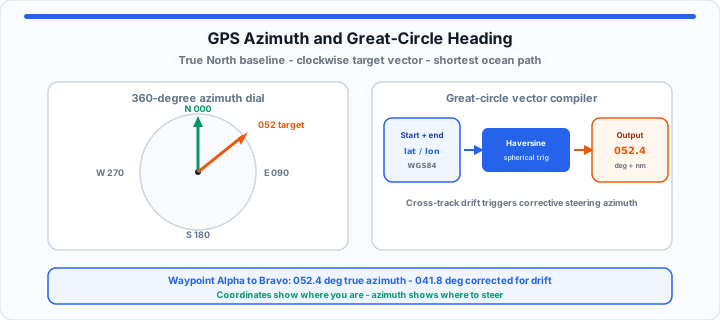
An azimuth measures horizontal direction relative to True North. True North provides an unchanging geodetic datum baseline. In my backcountry tracking experience, magnetic needles shift continuously. True North stays fixed on the geographic axis pole. Azimuth angles range from zero to three hundred sixty degrees. A bearing angle can change based on local references. An azimuth always references true zero degrees clockwise. When I plot a great-circle route, precision remains critical. Small steering errors multiply across long oceanic distances.
Modern satellite arrays track subtle hull rotations instantly. Dual antennas compute directional vectors without vessel forward movement. Multi-antenna GPS configurations eliminate magnetic needle swing errors. Gyrocompass backup systems align directly with satellite azimuth outputs.
Magnetic Declination Offsets
Magnetic north shifts due to fluid iron outer core movements. The difference between true north and magnetic north is declination. Geodetic survey teams must offset magnetic declination constantly. Ignoring declination drives ships miles off their course line. Local iron deposits also disrupt traditional shipboard magnetic compasses. GPS arrays bypass magnetic distortion by using orbital geometry. Internal lookup tables convert magnetic headings to true azimuth values.
True Bearing Grid References
Grid north aligns with artificial map projection lines. Grid lines distort true angles near earth polar regions. True bearing references actual planetary curvature without map distortion. Satellite navigation computers calculate true spherical vectors continuously. To get started, reference your cardinal headings against azimuth degrees.
| Compass Cardinal Direction | Quadrant Range | Exact Azimuth Degree Parameter |
|---|---|---|
| North (N) | Top Baseline | 000° / 360° |
| North-East (NE) | Upper Right | 045° |
| East (E) | Right Horizon | 090° |
| South-East (SE) | Lower Right | 135° |
| South (S) | Bottom Baseline | 180° |
| South-West (SW) | Lower Left | 225° |
| West (W) | Left Horizon | 270° |
| North-West (NW) | Upper Left | 315° |
Plot a route: Enter start and destination coordinates in the Azimuth Calculator for forward azimuth and great-circle distance, or use the Latitude Longitude Distance Calculator for haversine distance alone.
The Spherical Haversine Grid
Moving onto spherical space mechanics, flat paper charts lie. Flat maps distort straight lines across large marine distances. The shortest path across open ocean is a great-circle arc. Great-circle arcs curve visually when flattened onto flat paper charts. Your target azimuth angle shifts constantly along great-circle routes. A constant compass heading forms a rhumb line instead. Rhumb lines cover longer total distances than great-circle paths. GPS units recalculate initial azimuth angles every few meters. This continuous adjustment keeps vessels on true shortest routes.
You can map your spatial coordinate lines using this distance calculator. Satellite software calculates spherical trigonometry vectors at high speeds. Real-time updates compensate for atmospheric satellite signal delays.
Ellipsoidal Distance Variables
Earth is not a perfect smooth geometric sphere. Planetary rotation flattens the poles and bulges the equator. Geodetic systems use ellipsoidal models like WGS eighty-four. Ellipsoidal models refine true distance calculations across oceans. Precise distance calculations prevent unexpected fuel exhaustion on voyages. Surveyors measure elevation offsets to calculate true surface distance.
Cross-Track Error Boundaries
Cross-track error measures sideways drift from your planned path. Currents and wind force vessels away from target tracks. The navigation computer calculates corrective azimuth vectors instantly. This new steering angle head-intersects the original waypoint path. Setting tight cross-track boundaries triggers alarms during drift events. Automated steering systems correct rudder angles using azimuth data.
The initial true azimuth calculation uses spherical trigonometry math:
θ = atan2(sin(Δλ)·cos(φ₂), cos(φ₁)·sin(φ₂) − sin(φ₁)·cos(φ₂)·cos(Δλ))
Where variable φ₁ represents your starting latitude coordinate. Where variable φ₂ represents your target destination latitude coordinate. Where variable Δλ represents the total longitude coordinate difference. Plug your waypoint pairs into the Azimuth Calculator to verify the result without hand math.
The Real-World Open-Water Track Log
In practical environments, open water current drift causes severe deviation. Consider a motor vessel traveling between remote island waypoints. Strong equatorial currents push the vessel off its course line. The vessel must compute a fresh heading vector to compensate.
- Departure Waypoint Alpha: 12.0000° N Latitude, 65.0000° W Longitude
- Destination Waypoint Bravo: 14.5000° N Latitude, 61.2000° W Longitude
- Intended Great-Circle Azimuth: 052.4° True North Heading Vector
- Measured Ocean Drift Offset: 2.8 Knots Due South-East Drift
- Calculated Cross-Track Deviation: 4.2 Nautical Miles Starboard Drift
- Required Corrective Steering Azimuth: 041.8° True Compensated Heading
Adjusting steering to forty-one point eight degrees negates drift. The vessel recovers its original waypoint track before sunset. Continuous vector updates preserve safety during night transits. Captains monitor cross-track metrics to verify steering correction accuracy. Automated logging logs azimuth adjustments for later journey analysis. For speed-over-ground checks during drift events, cross-reference the Speed Calculator.
Open Azimuth Calculator Open Lat/Long Distance Calculator
Frequently Asked Questions
What is the difference between an azimuth and a bearing?
An azimuth references True North across a full 360-degree circle. A bearing measures angles relative to local references or quadrants.
How do GPS arrays calculate true heading while stationary?
Dual-antenna GPS arrays compare carrier phase signals between two sensors. This baseline phase offset identifies exact hull orientation while stationary.
How do you calculate azimuth from latitude and longitude?
Apply spherical trigonometry using starting and destination coordinate pairs. Pass latitude and longitude values into the inverse haversine formula.
Why does cross-track error alter your true target azimuth?
Sideways drift shifts your current position away from your baseline path. The array must calculate a new angle to reach target waypoints.
How does magnetic declination affect GPS azimuth readings?
Magnetic declination affects physical magnetic compasses rather than GPS arrays. Satellite receivers compute true azimuth directly from geodetic orbital coordinates.